PACKAGING MACHINE INTEGRATION

Checkweigher load cells for dynamic OEM weighing.

Match gross load, deck geometry and line timing. Review the reference designs, then validate the assembled machine.

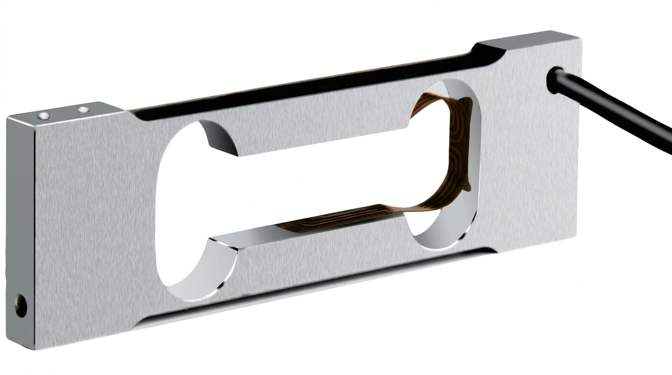
microcapacity aluminum parallel flexure open window beam visible strain gauge and side cable — supplier-source product reference
Product geometry reference; confirm the exact order configuration.

CAPACITY DOES NOT SET LINE SPEED

Five inputs before selecting a sensing beam.

A static calibration can pass while moving packs miss the required error band. Define the operating envelope before quoting a dynamic result.

Machine inputWhat to recordDecision it supports
Gross supported massMaximum product plus belt deck, hopper, fixtures and attachments.Rated load, tare allowance and handling-load review.
Product and deck geometryProduct length, centre-to-centre pitch, belt dimensions and load position.Time fully supported by the weigh section and eccentric-load envelope.
Line timingMinimum/maximum speed, acceleration, trigger positions and usable window in ms.Budget for entry transients, settling, filtering and a valid decision.
Target dynamic resultError band in g, throughput, product variation and reference-weight method.An acceptance test rather than an unsupported speed claim.
PLC and environmentTrigger/reject timing, required interface, vibration and cleaning exposure.Electronics selection and the complete integration scope.

The references below have documented static capacity, geometry and electrical values. Settling time, resonant frequency and dynamic error are not characterized here. Select a prototype-review candidate, then agree machine-level trials.

Compare the platform envelope before the electronics.

Two compact IP65 references cover 200 g–5 kg across their variants. The larger aluminum reference covers 50–500 kg. These are distinct static reference ranges, not a continuous qualified dynamic series.

microcapacity aluminum parallel flexure open window beam visible strain gauge and side cable — supplier-source product reference

SPL-CMP-101

Microcapacity open-flexure single point

Reference capacities
200 g–3 kg
Platform envelope
100 × 100 mm
Catalogue protection
IP65
Analog signal
0.8–1.0 mV/V; 405 ±5 Ω input bridge

Catalogue selection reference. Confirm the exact capacity, supplied drawing, environment and application acceptance.
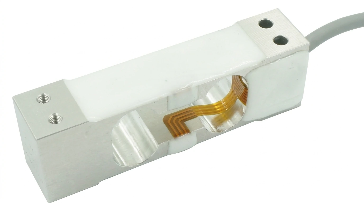
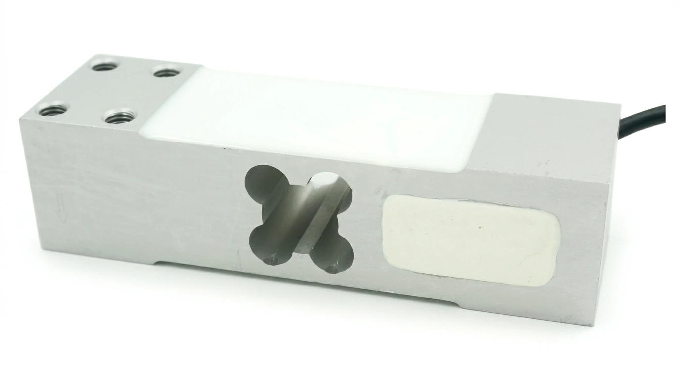
microcapacity compact aluminum parallel beam transparent flexure potting and side cable — supplier-source product reference

SPL-CMP-102

Compact potted-flexure single point

Reference capacities
300 g–5 kg
Platform envelope
200 × 200 mm
Catalogue protection
IP65
Analog signal
1.0 mV/V ±10% / 2.0 mV/V ±10%; 380 ±40 Ω input bridge

Catalogue selection reference. Confirm the exact capacity, supplied drawing, environment and application acceptance.
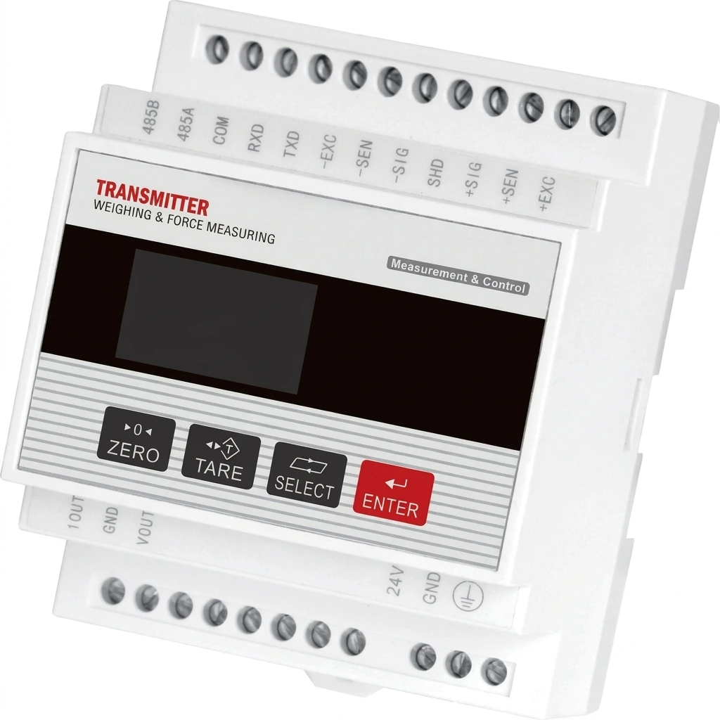
aluminum single point platform cell dual aperture four top mounting holes and black cable — supplier-source product reference

SPL-ALU-101

Large-platform aluminum single point

Reference capacities
50 kg–500 kg
Platform envelope
600 × 600 mm
Catalogue protection
IP67
Analog signal
2.0 mV/V ±10%; 420 ±20 Ω input bridge

Catalogue selection reference. Confirm the exact capacity, supplied drawing, environment and application acceptance.

Filter all 41 capacity-specific mounting configurations

MECHANICS → SIGNAL → DECISION

Sampling is one stage of the timing budget.

The flexure, moving tare and installation determine mechanical response. An amplifier and ADC acquire the bridge signal; filtering and PLC logic then determine when to accept or reject a product. A faster sample stream cannot remove a mechanical transient.

For multi-head weighers, record hopper tare, discharge shock and the individual head's cycle. For filling machines, include material impact, flow cutoff and post-cutoff settling. Keep each test tied to its real mounting and controller settings.

Include the line conditions in your RFQ
  1. 1 / SIGNAL STAGE

    Platform + sensor

    Tare, stiffness, vibration and entry/exit transients.

  2. 2 / SIGNAL STAGE

    Amplifier + ADC

    Excitation, input range and noise; samples are raw observations.

  3. 3 / SIGNAL STAGE

    Filter + valid weight

    Settling and filter latency; accept within agreed limits.

  4. 4 / SIGNAL STAGE

    PLC + reject timing

    Trigger, decision and actuation; validate the real machine.

Conceptual workflow, not a measured performance trace. ADC sample rate, filtered update rate and accepted weights/second are separate quantities. Open the flow diagram.
high speed load cell transmitter white din rail housing twin terminal rows and front display — supplier-source product reference
Reviewed electronics reference. Confirm the exact sampling, filtering, trigger and PLC-interface specification independently.

Specify the transmitter and reject interface separately.

Request bridge excitation, input range, noise, trigger latency, filtered update behavior and PLC communications for the selected instrument. RS485, analog outputs and industrial Ethernet options need exact hardware and firmware confirmation.

The pictured instrument does not establish integrated digital output in the load cell, or simultaneous support for every protocol. The RFQ's transmitter add-on is a request for a matched signal chain.

Freeze the sensor, cable and electronics revision together

Turn the prototype line trial into a release record.

Baseline the installed platform

Check zero, known weights, repeatability and centre/corner placement before running the belt. Record sensor, deck, cable, indicator settings and drawing revision.

Exercise the actual line envelope

Agree the sample set and number of passes. Test representative mass, pack position, speed changes and adjacent-machine vibration. Retain time-aligned weight and trigger data.

Approve error and reject timing

Agree limits for dynamic error, repeatability, false decisions and reject actuation. Record all filter and timing settings; recheck after a mechanical or firmware change.

For metrology scope, OIML lists load cells under R60 and automatic catchweighers under R51. A component declaration does not establish finished-machine approval.

Questions about dynamic response and approval scope

Does a 1,200 samples/s transmitter guarantee 1,200 weights/s?

No. ADC sampling, filtered updates and accepted product weights are separate rates. Mechanical settling, belt transitions, vibration, filtering and reject timing must fit the real weigh window. Confirm each instrument and interface specification.

Are these SPL references rated for a specific settling time?

No measured settling-time or natural-frequency envelope is published for these catalogue references. They are starting points for mechanical and electrical review. Agree a prototype line trial before committing to production performance.

Can a parallel beam replace a fluid-damped checkweigher sensor?

A common capacity or mV/V output is insufficient. Damping architecture, stiffness, load introduction, mounting, cable and dynamic behavior must be compared. No automatic fluid-damped replacement is claimed.

Does a C3 load cell approve the finished automatic checkweigher?

No. Component load-cell evidence and finished automatic catchweigher evaluation have different scopes. Confirm the exact model certificate and the applicable machine-level metrology requirements for the intended market.

For loads between the compact and larger aluminum references, review the stainless SPL-SSW-101 reference (3–200 kg) or request another capacity. It is also a static reference; no dynamic response is established.

The two compact catalogue designs use short 350 mm / 400 mm, four-wire cables. Confirm controller distance, cable length and the indicator arrangement before changing the lead. Request a suitable six-wire configuration when excitation sensing is needed; do not infer it from an electronics add-on.

DYNAMIC OEM REVIEW

Send the timing envelope with the load.

Include belt speed, product pitch, deck geometry, usable window and allowed dynamic error. Attach the mounting and controller diagrams in your own email application after copying the brief.

Request a matched overload-stop base and transmitter where useful. Prototype availability, price and the trial plan are confirmed after configuration review.

ENGINEERING RFQ / SPL selection

Build your weighing module.

Prototype, small batch or scheduled OEM supply.

Dynamic checkweigher — project inputs

Optional engineering requirements for this review. Values describe your application; they do not establish a qualified sensor rating.

Mounting, signal and approval requirements

These are requested configurations, not confirmed availability or approval.

Request integration options

Budget targets for configuration review, not a firm quote; freight, duties and prototype/custom setup are quoted separately. Interfaces, sample rate and metrological evidence depend on the selected equipment. A test report is not an OIML certificate.

Send drawings directly to [email protected].

Review, copy or email your engineering brief

For a browser-based company mailbox, copy this brief and attach drawings or nameplate photos in your own email application. If the pre-filled draft does not open completely, paste the full copied brief into your company email.

Open pre-filled RFQ email