LOAD PATH / SPACERS / OVERLOAD STOPS
Leave the flexure free. Control the travel.
A good single point base directs load through the designated fixing and loading faces, while keeping the active beam and its cable clear of the frame.
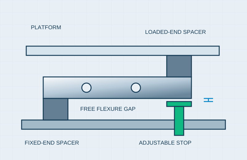
Spacer plates establish the working gap.
Use rigid, flat contact faces at the manufacturer-defined mounting pads. Provide enough clearance for the active flexure at maximum normal deflection, allowing for manufacturing tolerances and frame movement.
Keep screws within the allowed engagement depth. Tightening torque and fastener grade must follow the selected sensor’s drawing and the joint materials; a universal high-strength bolt choice is not sufficient.
Set overload stops from measured deflection.
The stop must remain clear throughout normal operation, including tare and permitted corner loads. It must engage before the sensor exceeds its allowed travel under the agreed overload cases. Both requirements need a tolerance and stiffness review.
A blanket “full-scale deflection + 0.2 mm” gap is not a validated design rule. Use the specific load cell data, base stiffness, temperature effects and stop geometry; verify the setting with controlled loads.
Center and corner stops protect different load cases. Impact energy, stop stiffness and how the platform contacts the stops govern peak force. Stops do not guarantee survival of an arbitrary dropped mass.
A loaded-end vertical stop does not establish corner-impact protection. Review corner stops and torsional load cases against the actual platform and frame. A factory-fixture corner-load report does not replace verification on the assembled machine.
Capacity includes the empty platform.
Begin with gross load = platter tare + maximum product load + attached tooling. Then assess dynamic forces and permitted eccentricity against the selected model’s limits. Do not confuse display resolution with metrological accuracy.
Prove the assembled platform at the center and corners.
- Confirm clean mounting surfaces, flatness and the correct fastening sequence.
- Inspect free flexure clearance and cable routing through the full working travel.
- Calibrate at the stated reference conditions.
- Test repeatability and corner-load response with an agreed load and placement pattern.
- Verify stop engagement separately using a controlled procedure that respects sensor limits.
- For dynamic weighing, repeat validation at the actual belt speed, filter settings and cycle timing.
Request a matched SPL-BASE module.
Start from 300 × 300, 400 × 500 or 600 × 600 mm frame requests. Specify the platen, sensor, leveling feet, spacer pack and stop arrangement together, including drainage and washdown requirements.
Review the base-frame configurationInstallation reference: HBM PW15AH mounting instructions. Follow the actual supplied sensor instructions; this guide does not replace them.
CAPACITY + PLATFORM + ENVIRONMENT
Specify the entire load path.
Send the platform size, gross load, mounting drawing and production quantity.